
Build your first model
What are the six steps? Remind yourself with our handy infographic
Step 1: Create a new model file
- Open Anaqsim on your computer
- Go to File > Save As
- Give your new model a name
Step 2: Define your vertical layers
This is where you’ll create the foundation of our model
- Go to the Model Input menu > Domains > Confined/Unconfined
- Fill in the input boxes as below
- Click Save (File > Save)
Now you have a 23m thick unconfined aquifer. Don’t worry about the “average head” value – It’s just a starting point that you can easily change

Step 3: Input horizontal boundaries
Now we will define the aquifer’s shape – which is simply the classic box for this model.
Defining head-specified boundaries (east and west boundaries)
- Go to Model Input > Line Boundaries > Head Specified
- Add two boundaries by copying the details below (to copy the co-ordinates to your clipboard, click the relevant link). All other boxes can be left as default values
- Click Save (File > Save)
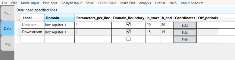
Defining no-flow boundaries (north and south boundaries)
- Go to Model Input > Line Boundaries > Normal Flux Specified
- Repeat the process of copying and pasting co-ordinates and other boundary details
- Click Save

Adding wells
Let’s add some action to our model!
- Go to Model Input > Pumping Wells > Discharge-Specified
- Add two wells: one injection well and one production well
- Copy the details from the image below (not positive and negative signs)
- Click Save

Step 4: Enable recharge nodes
For the classic box model, precipitation recharge is usually ignored. So we will not add recharge, but go through the steps and add zero recharge so you get familiar with the process.
- Go to Model Input > Area Source/Sink > Uniform, Domain
Step 5: Run the model
You have built your first model. Now for the exciting part!
- Click Solve on the main menu bar
Anaqsim will run the simulation instantly. Look at the run log to see the simulation documented. That’s it – the model is complete!
Step 6: View and analyze your results
This is where you get to see your model come to life!
- Anaqsim’s Plot view starts with a blank slate, so let’s tell it what to display. Go to Plot Input > What to Plot and check the boxes for ‘Contours’ and ‘Vectors’
- Click Make Plot > All Selected Features Same Level / Time
You should now see the simulated interaction between the injection and production wells within the groundwater flow field you defined
Congratulations! You have just created a functional AEM model, simulated groundwater flow and visualized the results.
Where next in our Getting Started Guide?
Get Connected
Quick Start Guide
Build Your First Model
You are here!
Build Your Second Model
Free 14-day trial
No credit-card required